|
|
|
Kto jest w sklepie?
Sklep przegląda 5703 gości i
2 zarejestrowanych klientów |
|
Kategorie
|
|
Informacje
|
|
Polecamy
|
|
|
 |
|
|
Dla tego produktu nie napisano jeszcze recenzji!
 ;
Szybko, sprawnie i tanio. Serwis godny polecenia. Będę polecał innym
 ;
Ogólnie jest OK, z wyjątkiem obrazu płyty głównej, który jest miejscami mało czytelny, ale można sobie poradzić.
;
Dokładna dokumentacja, pomogła w szybkiej naprawie telewizora. Dziękuję!
;
jedyne do czego mogę mieć zastrzeżenie to jakość zdjęć zawartych w przesłanej instrukcji serwisowej ponieważ są fatalnej jakości, praktycznie nieczytelne. tak poza tym jestem zadowolony to jest to czego szukałem.
;
Wszystko w porządku.
Instrukcja czytelna i kompletna.
Dziękuję.
all right!
thank you.
Circuit Descriptions and Abbreviation List
Beam-current Correction The �EHT-info� signal at point 10 of the LOT, depends on the value of the beam-current and the voltage from divider R3450, R3451 and C2450. This signal is fed to the HOP to trim the contrast, and to compensate for the changes in picture-width as a function of the EHT-info, when EHT is decreased. The �EHT-info� is also used to correct the EWcurrent.
The �DYN-FASE-CORR� signal, derived from the �EHT-info� signal, is fed to the HOP via C2455 and drives a dynamic phase correction necessary because of beam-current variations. This is done by regulating TON of the line transistor TS7421.
EM3E
9.
GB 105
9.10.4 Secondary Line Voltages During the blocking time of TS7421, the magnetic energy of coil 1 - 5 of the LOT, is transferred to electrical energy in the secondary winding. Via rectifying and smoothing, the several secondary supply voltages are generated, like: � EHT, Focus and Vg2-voltage � +200V for the CRT panel (pin 8 LOT) � � � � +11D for the line deflection (pin 12 LOT) +13VLOT for the frame deflection (pin 6 LOT) -15VLOT for the frame deflection (pin 3 LOT) Filament voltage (pin 9 LOT)
9.11 Vertical (Frame) Deflection (diagram A4)
9.11.1 Frame Stage Drive
+8V HOP +11V
COLD
HOT
V-SHIFT 3628
TDA 7052 TILT 25 1620 ROTATION COIL 3640 +8V 5621
V-SHIFT 3642
3631 +13VLOT
+8V
3407 FRAME DEFL. COIL -15VLOT 3623
2 FDFRAME 1 FD+
7440-A 7450-A 7641 3639
HFB-X-RAY-PROT
7455
+8V 7450-B 2653 3620
E/W
3
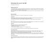
E/W DRIVE 1 7482 2 4 CL 16532044_021.eps 140501 5 E/W E/W
Figure 9-12 The HOP drives the frame output stage with a symmetrical saw-tooth voltage. As the HOP is 'cold' and the frame output stage is 'hot', they are galvanic isolated. This is done via a transformer (5621). As in the MG-chassis, the HOP generates 3 signals needed for the frame output stage: FRAMEDRIVE+, FRAMEDRIVE- and TILT (for rotation). The rotation circuit is kept at the �cold� side of the chassis, to avoid the costs an extra optocoupler. The circuit around IC7440 will amplify this signal and the output current will flow through the rotation coil. 9.11.2 Flyback Generator The frame output stage is supplied via the +13 V and -15 V coming from the LOT. The output of the amplifier is 0 VDC, so a coupling capacitor is not required. During the (forward) scan, a supply of +13 and -15 V is sufficient to respond to the slow changing current. The internal flyback generator puts a voltage of -15 V on pin 3. Because of the voltage drop over zener diode D6622 (8.2 V), C2622 will be charged to 19 V: being 13 + (15 - 8.2 - 0.7) V. During the flyback scan, the change in current-per-time is much larger, so a higher voltage is required. The flyback generator will now generate a voltage of +13 V on pin 3. Added to the charge on C2622 this will give a flyback voltage of 32 V (depending on the CRT size, this value can differ).
The amplifier IC (IC7620, pin 5) supplies the saw-tooth current to the frame deflection coil. The current through this coil is measured via R3620//R3621//R3622 and fed back to the inverting input of the amplifier. R3624 and C2624 on the output of the amplifier, form a filter for high frequencies and in that way also prevents oscillations. Peak voltages on the output, e.g. as a result of a possible flash, are damped by the clamp circuit consisting of D6619, C2627 and R3627. The network consisting of R3625, R3626, R3629 and C2629 form an extra damping circuit. 9.11.3 Protection circuits
Bridge Coil Protection The secondary voltage of the bridge coil L5422, is guarded at the diode modulator (D6421/6422) via a 10 V zener diode (6499 on diagram A3). When the bridge-coil is working properly, the average voltage on D6422 is such that this zener diode will conduct. It will drive TS7652 into saturation. When, for any reason, the secondary side of the bridge coil is shorted, the average voltage on D6422 will drop below the zener-voltage, and TS7652 will block. Now capacitor C2642 is charged. Transistor TS7407 starts conducting and the SUP-ENABLE signal is grounded via R3403. This will switch �off� the main supply (see diagram A1).
|
|
|
> |
|