|
|
|
Kto jest w sklepie?
Sklep przegląda 5893 gości |
|
Kategorie
|
|
Informacje
|
|
Polecamy
|
|
|
 |
|
|
Dla tego produktu nie napisano jeszcze recenzji!
 ;
Bardzo dobra jakość skanu, przystępna cena. Instrukcja serwisowa okazała się przydatna przy "reanimowaniu" dwudziestoparoletniego decka, który teraz pięknie gra :)
;
...instruction is ok.
...instrukcja jest ok.
Thanks/Dzięki
;
Documentation made available quickly and It is good quality. Thanks.
EN 144
9.
FM23, FM24, FM33
Circuit Descriptions, List of Abbreviations, and IC Data Sheets
By comparing the input voltage to a triangle wave, the amplifier increases duty cycle to increase output voltage, and decreases duty cycle to decrease output voltage. The output transistors (item 7365 on diagram A3) of a Class D amplifier switch from "full off" to "full on" (saturated) and then back again, spending very little time in the linear region in between. Therefore, very little power is lost to heat. If the transistors have a low "on" resistance (R_DS(ON)), little voltage is dropped across them, further reducing losses. A Low Pass Filter at the output passes only the average of the output wave, which is an amplified version of the input signal. In order to keep the distortion low, negative feedback is applied (via R3308). A second feedback loop (via R3310) is tapped after the output filter, in order to decrease the distortion at high frequencies. The advantage of Class D is increased efficiency (= less heat dissipation). Class D amplifiers can drive the same output power as a Class AB amplifier using less supply current. The disadvantage is the large output filter that drives up cost and size. The main reason for this filter is that the switching waveform results in maximum current flow. This causes more loss in the load, which causes lower efficiency. An LC filter with a cut-off frequency less than the Class D switching frequency (350 kHz), allows the switching current to flow through the filter instead of the load. The filter is less lossy than the speaker, which causes less power dissipated at high output power and increases efficiency in most cases. 9.5.5 Mute (Diagram A2 to A6) A mute switch (item 7302) is provided at the PWM inputs (item 7315, LM311). This switch is controlled by the AUDIO_ENABLE line, which checks the availability of the +9V_STBY voltage. 9.5.6 Protections Short-circuit Protection (Diagram A3) A protection is made against a too high temperature of transistor 7355 in case of a short-circuit of output FET 7365-1. Transistor 7340 is sensing the current through transistor 7355 via R3355, and activates the DC-protection line (see figure "DC protection") in case the current becomes too high. This is the same for all four amplifier parts. DC-protection (Diagram A7)
+9V_STBY 5753
In order to guarantee this good bass performance, the closed box has to be airtight. This is achieved by a closely fitting foam ring between the front and back part of the cabinet. 9.5.2 Supply (Diagram A7) The supply voltage is a symmetrical voltage of +/- 14.5 V_dc, generated by the main supply via L5002. � V_SND_POS on connector 0302 pin 5/6, and � 9.5.3 V_SND_NEG on connector 0302 pin 1/2.
Filter (Diagram A2) Electrical filtering is needed for following reasons: � Limiting the cone excursion, thereby reducing the distortion. � Increasing the power handling capacity (PHC). In this amplifier panel, active second order Sallen-Key filters are used, with crossover frequencies of 1 kHz for the low pass filter, and 3 kHz for the high pass filter. The audio signals are filtered before the amplifier. There are some reasons for doing this: � It is now easy to do active filtering, and � At less costs (no expensive coils and capacitors). Low Pass Filter (LPF) For L and R separately, a Low Pass Filter (IC7238A and B) is processing L_LOW and R_LOW. The output signal of this filter is then fed to the audio amplifier (identical for right channel). High Pass Filter (HPF) For L and R separately, a High Pass Filter (IC7260A and B) is processing L_HIGH and R_HIGH. The output signal of this filter is then fed to the audio amplifier (identical for right channel).
9.5.4
Amplifier (Diagrams A3 to A6) Each speaker has its own 15 W class-D amplifier. These socalled SODA (Self Oscillating class-D Amplifier) amplifiers combine a good performance with a high efficiency, resulting in a big reduction in heat generation. Principle Audio-power-amplifier systems have traditionally used linear amplifiers, which are well known for being inefficient. In fact, a linear Class AB amplifier is designed to act as a variable resistor network between the power supply and the load. The transistors operate in their linear region, and the voltage that is dropped across the transistors (in their role as variable resistors) is lost as heat, particularly in the output transistors. Class D amplifiers were developed as a way to increase the
A OUT_LH
OUT_LL
VCC_10_POS
2753
3752 7735
3770
3771
3775 3750 7751
3751 7761
3754 DC_PROT 7755
efficiency of audio-power-amplifier systems.
3780 3781 2760 3765 3760
+V
OUT_RH OUT_RL VCC_10_NEG CL16532099_001.eps 200801
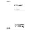
Figure 9-20 DC Protection
-V CL16532099_002.eps 200801
Because of the symmetrical supply, a DC-blocking capacitor, between the amplifier and the speaker, is not necessary. However, it is still necessary to protect the speaker for DC voltages. The following protections are therefore implemented: � Via R3765 and R3775, each stabilised supply voltage line (via items 7735 and 7745) is checked on deviations. � Via R3770/3771/3780/3781, each amplifier output is checked for DC-voltage.
Figure 9-19 Principle Class-D Amplifier The Class D amplifier works by varying the duty cycle of a Pulse Width Modulated (PWM) signal.
|
|
|
> |
|