|
|
|
Kto jest w sklepie?
Sklep przegląda 5906 gości |
|
Kategorie
|
|
Informacje
|
|
Polecamy
|
|
|
 |
|
|
Dla tego produktu nie napisano jeszcze recenzji!
 ;
...instruction is ok.
...instrukcja jest ok.
Thanks/Dzięki
;
Documentation made available quickly and It is good quality. Thanks.
Alignments
L04E AB
8.
EN 71
8. Alignments
Index of this chapter: 1. General Alignment Conditions 2. Hardware Alignments 3. Software Alignments and Settings Note: � The Service Default Mode (SDM) and Service Alignment Mode (SAM) are described in chapter 5 �Service Modes, ...�. � Menu navigation is done with the CURSOR UP, DOWN, LEFT, or RIGHT keys of the remote control transmitter. SATURATION/COLOR to �0�. CONTRAST to �0�. BRIGHTNESS to minimum (OSD just visible). Return to the SAM via the MENU key. Connect the RF output of a pattern generator to the antenna input. Test pattern is a 'black' picture (blank screen on CRT without any OSD info) with a signal strength of 1 V_pp. 10. Set the channel of the oscilloscope to 50 V/div and the time base to 0.2 ms (external triggering on the vertical pulse). Ground the scope at the CRT panel and connect a 10:1 probe to one of the cathodes of the picture tube socket (see diagram B). 11. Measure the cut off pulse during first full line after the frame blanking (see figure �V_cutoff waveform�). You will see two pulses, one being the �cut off� pulse and the other being the �white drive� pulse. Choose the one with the lowest value; this is the �cut off� pulse. 12. Select the cathode with the highest V_dc value for the alignment. Adjust the V_cutoff of this gun with the SCREEN potentiometer (see figure �Top view family board�) on the LOT to 160 V_dc, except for the 25/28BLD picture tube (Black Line Display, for EU only); this tube must be aligned to 140 V_dc. 13. Restore BRIGHTNESS and CONTRAST to normal (= 31). 5. 6. 7. 8. 9.
8.1
General Alignment Conditions
Perform all electrical adjustments under the following conditions: � AC voltage and frequency: 120 V_ac / 60 Hz or 240 V_ac / 50 Hz (region dependent). � Connect the set to the Mains voltage via an isolation transformer with a low internal resistance. � Allow the set to warm up for approximately 20 minutes. � Measure the voltages and waveforms in relation to chassis ground (with the exception of the voltages on the primary side of the power supply). Never use the cooling fins / plates as ground. � Test probe: Ri > 10 Mohm; Ci < 2.5 pF. � Use an isolated trimmer / screwdriver to perform the alignments.
max.
8.2
Hardware Alignments
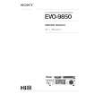
0V Ref.
VCUTOFF [VDC]
E_06532_011.eps 110204
Figure 8-2 V_cutoff waveform
C 1504 1506
8.2.2
Focusing 1. Tune the set to a circle or crosshatch test pattern (use an external video pattern generator). 2. Choose picture mode NATURAL (or MOVIES) with the SMART PICTURE button on the remote control transmitter. 3. Adjust the FOCUS potentiometer (see figure �Top view family board�) until the vertical lines at 2/3 from east and west, at the height of the centreline, are of minimum width without visible haze.
7990
7601 9275 SDM 9252 1221 A 5512 B Focus Screen VG2 LOT
1204
1000 (TUNER)
D 1005 ComPair E_14480_030.eps 130204
Figure 8-1 Top view family board 8.2.1 Vg2 Adjustment 1. Activate the SAM. 2. Go to the WHITE TONE sub menu. 3. Set the values of NORMAL RED, GREEN and BLUE to �32�. 4. Go, via the MENU key, to the normal user menu and set
|
|
|
> |
|